10+ lead/lag pump control wiring diagram
Franklin Well Pump Control Box Wiring Diagram - Search Best. Wiring Diagrams Sometimes Called Main Or Construction Diagrams Show The Actual Connection Points For The Wires To The Components And Terminals Of The Controller.
Lead Lag Pump Alternation Control Precision Digital
If using single action switches with a control panel please.

. Wiring diagram to connect 110 v single phase pumps up to 075 kw 1. Wiring diagram pump lead lag control boiler belimo multiple water hydronic systems low sr lf24 cut safgard sample fire system How To. A wiring diagram is a simplified standard pictorial depiction of an electrical circuit.
If the water level rises fs 2 will close first but the motor will not. Trying to configure logic for leadlag for 2 pumps P1 P2 and need to develop a logic diagram. Submersible wiring diagram pump control box wire phase single.
As shown in the. Use Relays In Your Wiring Projects. Nov 30 2007.
Provides Automatic Operation And Run Dry Protection. 0E60C1D Nissan Elgrand Fuse Box Translation. Sump pump control panel wiring diagram.
A wiring diagram is a simplified traditional. 10 Images about Automatic Submersible Water Pump Controller Circuit. If The Water Level Is Low Both Float Switches Are Normally Open.
Secondly connect the supply to input wire connectors following the. Wiring pump diagram submersible control well sump box panel lag lead phase single electrical. 0E21949 Land Rover Wiring Harness Damage.
Leadlag pump control wiring diagram Sabtu 22 Oktober 2022 This relay will alternate two compressors and provide a leadlag function with two pressure switches. Wiring diagram for connection of single phase 220v pumps up to 11 kw. Lead lag pump control wiring.
Simplex sump pump control panel wiring diagram from. 14EC032 Mazda 3 Fuse Box. 0C007BC Mack Truck Mirror Heaters Wiring Diagram.
Single phase water pump wiring diagram a dpst switch a resistible thermal overload and a capacitor are used in the submersible pump control box. Tighten screws on terminal block. Lead Lag Pump Control Wiring Diagram Free Wiring Diagram A wiring diagram is an easy visual representation in the physical connections and physical layout of an electrical system or.
Establish a connection between supply to input wire conductor. 1020EB2 Nissan 720 Stereo Wiring. The wiring diagrams illustrated in this installation manual represent a sampling of the many ways the iO-LL can be applied for leadlag control.
Automatic Submersible Water Pump Controller Circuit. Thermostat Pump Diagrams Wire Trane Lennox Hubs Coleman Kicking Bard Imageservice Notch. Low Level to Switch to shutdown pumps P1 and P2.

How To Program Lead Lag Pumping In Ignition Corso Systems
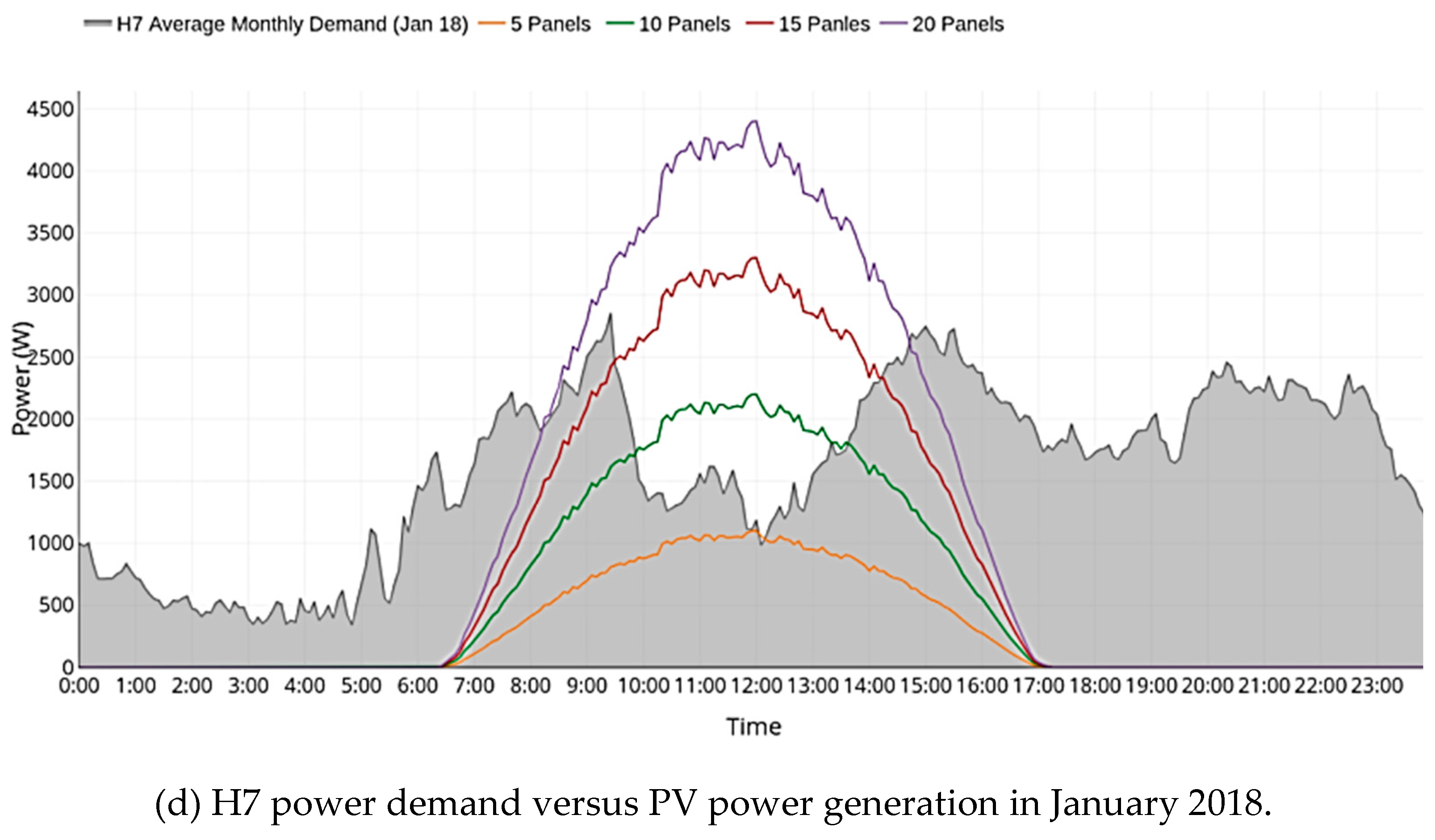
Energies Free Full Text High Resolution Household Load Profiling And Evaluation Of Rooftop Pv Systems In Selected Houses In Qatar Html

Submersible Pump Control Box Wiring Diagram For 3 Wire Single Phase Submersible Pump Submersible Well Pump

Electrogage Pump Controller Eg Controls

Control Panel Wiring Pump Control Panel Wiring Diagram How To Read Single Line Diagram Youtube
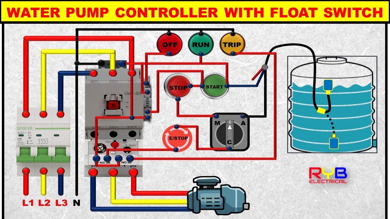
3 Phase Dol Starter Control And Power Wiring Diagram Water Pump Controller With Float Switch Youtube

Basic Motor Control Pump Panel Wiring Part 2 Youtube

Vertical Multi Stage Booster
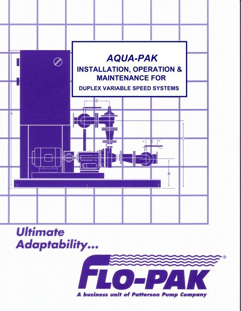
Duplex Variable Speed Systems Patterson Pump Company

Soft Actuator Materials For Electrically Driven Haptic Interfaces Ankit 2022 Advanced Intelligent Systems Wiley Online Library
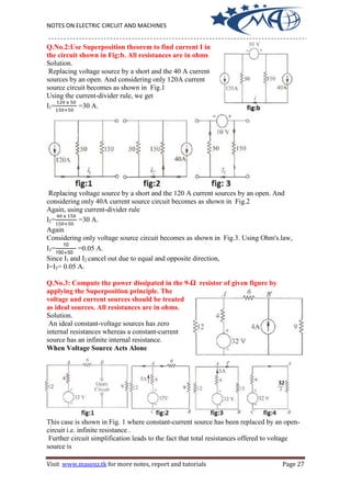
Electrical Ciircuit Mechine

Bode Diagram Of Original Lead Lag Disturbance Compensator Download Scientific Diagram

Untitled

Duplex Pump Control With A Single Float Switch Apg
Lead Lag Pump Alternation Control Precision Digital

How To Program Lead Lag Pumping In Ignition Corso Systems

Submillimeter Array Wikiwand